|
|
|
|
|
It was originally thought that short stator linear motor systems would be less costly - This is evidenced by the fact that many projects used the short stator design such as the Vancouver Light Rail system, Kuala Lumpur Transit, JFK AirTrain, Detroit People Mover and the Scarborough Light Rail in Toronto. However, the long-stator design is less costly when comparing total system costs. Long stator designs put power in the track, so that there is no need for "hot" third rail designs with needed security fencing, and no electrical brushes to wear out and limit vehicle speed. |
||
|
|
|
|
Linear Motors
There are no affiliations between Union Pacific Railroad and Magnetic Transport Systems and none are implied.
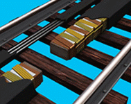
As shown in photo above, linear motors are nothing more than a conventional rotary motor with the field laid flat.
Linear Induction and Linear Synchronous Motor Systems
Linear motors can be divided into two basic motor drive systems and two motor orientation systems. The motor drive systems are:
- Linear induction motors (LIM); and
- Linear synchronous motors (LSM).
Both are referred to as a type of linear motor. And the orientation is either:
- A long stator linear motor; or
- A short stator linear motor.
The linear induction motor was invented in 1905, while linear synchronous motors came along in the early 1970’s as a major refinement to the original linear induction design.
Linear induction motors have a winding that when energized by an electric current reacts against a conducting plate through eddy currents that repel and push the conducting plate away from the windings. The amount of energy created is in direct relationship to the distance between the windings and the conducting plate and decreases by the square of the distance so if one increases the distance between the winding and the plate from ¼ inch to ½ inch, the motive force is 1/4th as much energy. Therefore, linear induction motors require a very close tolerance between the vehicle and the track increasing the required guide-way precision and therefore the cost.
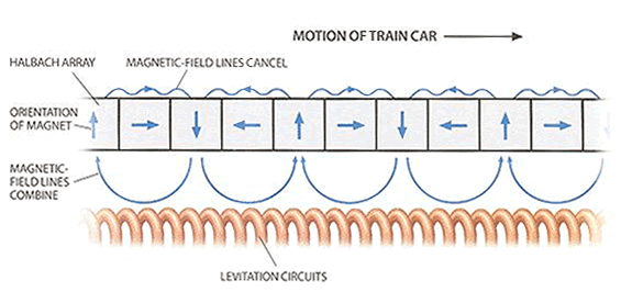
Linear synchronous motors replace the conducting plate with an array of magnets thereby reducing the need for such close tolerances and moving the magnets synchronously by locking onthe the magnetic wave. Recent advances developed for atomic accelerators where the magnetic force is doubled on one side of the magnet and cancelled out on the other, known as the Halbach array, have been utilized in some advanced linear motor systems substantially increasing the motors efficiency and levitating power. Add to this the latest discoveries in permanent Neodymium magnets and the most effective and most powerful system can now be economically developed.

Advantages of a Linear Motor Drive System
Both linear induction and linear synchronous motors can be oriented as long stator or short stator motors. The stator in conventional motors is generally considered the stationary part of the motor, but for linear motors it generally refers to the part of the motor that is energized to create motion.
A short stator motor is one where the stator is short because it is on the vehicle and the reaction plate or magnetic array is located on the guide-way. The location of the stator which must be energized to create motion determines where the power source must come from. Therefore on a short stator motor the power source must be on the vehicle. In order to get power to the vehicle some form of contact is required either through a brush contact on a third rail or overhead catenary wires.
On a long stator motor the stator is on the guide-way so it must be energized from a power source attached to the guide-way and the vehicle is dumb meaning it has no electronics or power source on board but only the conducting plate on LIM’s and the magnet array on LSM applications. The resulting differences between a long and short stator linear motor are significant. Long stator motors reverse the architecture and have the motor windings on the guide-way and the conducting plate on the vehicle. This eliminates the need for the hot third rail to power the system, eliminates the safety fencing requirement and eliminates the conducting brushes. Energy to run onboard systems such as lighting, air conditioning and other electrical needs comes from the reaction of the onboard magnets with the motor windings in the guide-way so long as the vehicle is moving. While stopped, the vehicle must utilize battery power to run any onboard accessories.
It was originally thought that short stator linear motor systems would be less costly because the guide-way could be a passive conducting plate and all of the electronics would be onboard the vehicle. This is evidenced by the fact that many of the original linear motor transportation projects used the short stator design such as the Vancouver Light Rail system, Kuala Lumpur Transit, JFK AirTrain, Detroit People Mover and the Scarborough Light Rail in Toronto. When comparing the systems costs, consideration must be given to the cost for an electrified third rail because power was required on board the vehicle and the need for safety fencing to protect trespassers from electrocution. Another design challenge was the fact that short stator design also required an electronic brush system where a conductor brushed along the third rail or catenary to pick up electricity to run the system. This creates maintenance problems as the brushes wear out and limit the top speed of the system to about 90 miles per hour.

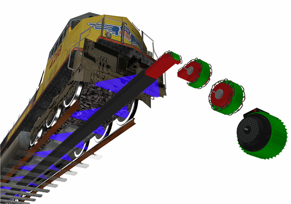
Innovative Transportation Systems and General Atomics have determined that the most advantageous system for the purposes described herein is a long stator linear synchronous motor architecture, similar to the one illustrated in the image on the right.

